
- Arduino uno pinout schematic serial#
- Arduino uno pinout schematic software#
- Arduino uno pinout schematic Pc#
Arduino uno pinout schematic serial#
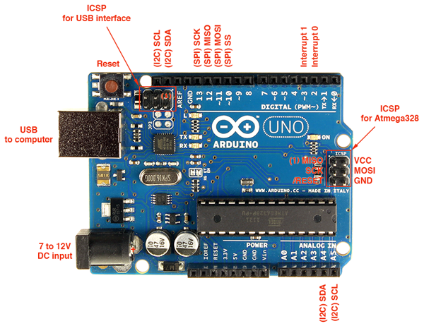
ICSP (in-circuit serial programming) headers can be utilized for programming ATmega microcontroller directly with the boot loader. Equivalent pins with the SPI library is employed for the communication of SPI. The CLK pulse synchronizes data transmission that is generated by the master. This pin is a serial CLK, and the CLK pulse will synchronize the transmission of which is produced by the master. This is the master out slave in the pin, used to transmit the data to the devices The SPI communication includes MOSI, MISO, and SCK. In this, both the SCL and SDA are CLK signal and data signal. These pins are mainly used in UART TTL serial communication.Īn Arduino UNO board employs SDA pin otherwise A4 pin & A5 pin otherwise SCL pin is used for I2C communication with wire library. The communication protocols of an Arduino Uno include SPI, I2C, and UART serial communication.Īn Arduino Uno uses the two functions like the transmitter digital pin1 and the receiver digital pin0. This pin brings a low line for resetting the microcontroller, and it is very useful for using an RST button toward shields which can block the one over the Arduino R3 board. The TWI pins are SDA or A4, & SCL or A5, which can support the communication of TWI with the help of Wire library.Īn analog reference pin is the reference voltage to the inputs of an analog i/ps using the function like analog Reference().

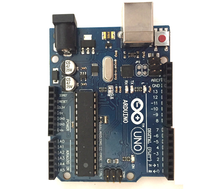
Whenever the digital pin is high, the LED will glow otherwise it will not glow. The SPI pins are 10, 11, 12, 13 namely SS, MOSI, MISO, SCK, and these will maintain the SPI communication with the help of the SPI library.Īn arguing board is inbuilt with a LED using digital pin-13. The PWM pins of an Arduino are 3, 5, 6, 9, 10, & 11, and gives an output of an 8-bit PWM with the function analog Write (). The external interrupt pins of the board are 2 & 3, and these pins can be arranged to activate an interrupt on a rising otherwise falling edge, a low-value otherwise a modify in value The connection of these pins can be done with the equivalent pins of the ATmega8 U2 USB to TTL chip. The serial pins of an Arduino board are TX (1) and RX (0) pins and these pins can be used to transfer the TTL serial data. Additionally, some of the pins of an Arduino include specific functions. The maximum current on any pin is 40mA which cannot surpass for avoiding the microcontroller from the damage. These pins can operate with 5V, and every digital pin can give or receive 20mA, & includes a 20k to 50k ohm pull up resistor. We know that an arguing Uno R3 includes 14-digital pins which can be used as an input otherwise output by using the functions like pin Mode (), digital Read(), and digital Write(). The memory of an ATmega328 microcontroller includes 32 KB and 0.5 KB memory is utilized for the Boot loader), and also it includes SRAM-2 KB as well as EEPROM-1KB. This board includes 14 digital input/output pins, Analog inputs-6, a USB connection, quartz crystal-16 MHz, a power jack, a USB connection, resonator-16Mhz, a power jack, an ICSP header an RST button. From these pins, 6-pins can be utilized like PWM outputs. The Arduino Uno R3 pin diagram is shown below.

Length and width of the Arduino are 68.6 mm X 53.4 mm.Flash Memory -32 KB, and 0.5 KB memory is used by the boot loader.The recommended input voltage ranges from 7V to 12V.The Operating Voltage of the Arduino is 5V.It is an ATmega328P based Microcontroller.The Arduino Uno R3 board includes the following specifications. Arduino Uno R3 Arduino Uno R3 Specifications The Uno-board is the primary in a sequence of USB- Arduino boards, & the reference model designed for the Arduino platform.
Arduino uno pinout schematic software#
Arduino board and IDE software are the reference versions of Arduino and currently progressed to new releases. The R3 Arduino Uno is the 3rd as well as most recent modification of the Arduino Uno. The term Uno means “one” in the language of “Italian” and was selected for marking the release of Arduino’s IDE 1.0 software.
Arduino uno pinout schematic Pc#
It includes the whole thing required to hold up the microcontroller just attach it to a PC with the help of a USB cable, and give the supply using AC-DC adapter or a battery to get started. Arduino Uno R3 is one kind of ATmega328P based microcontroller board. The Official Arduino Uno Rc Schematics Diagram 14core Com Basic Circuit Diagram Of Arduino Uno R3 Easyeda Build Your Own Arduino Bootload An Atmega Microcontroller 74hc595 With Arduino Uno R3 6 Steps Instructables


 0 kommentar(er)
